Integrating a Serial Camera (Generic)
https://support.cyanview.com/docs/Integrations/Generic/SerialCamera
The CI0 interface lets you control serial cameras (cameras controlled over a serial link) from your RCP over an IP network.
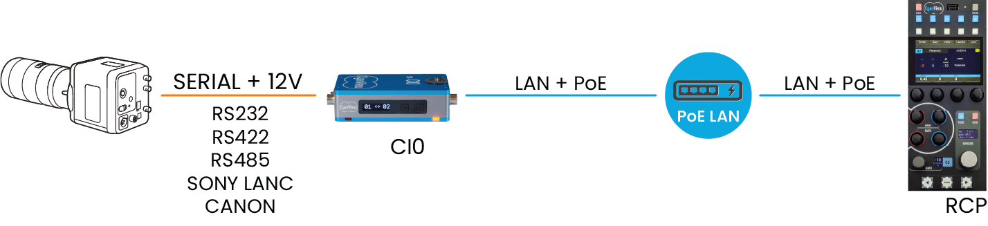
Required Equipment
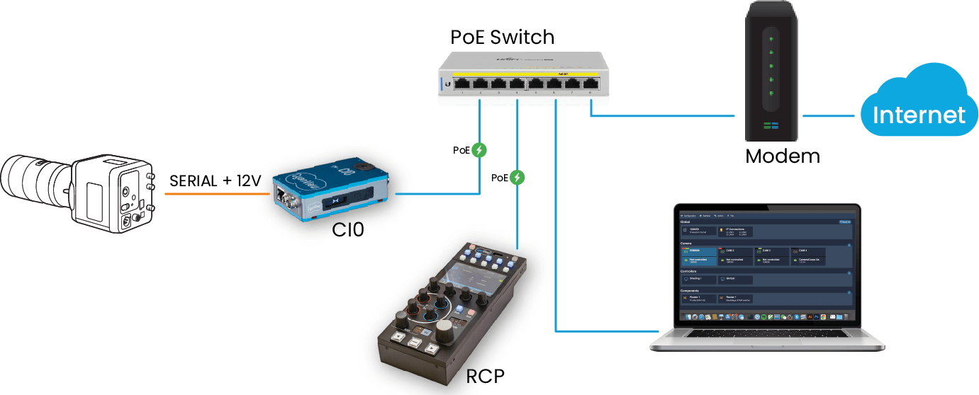
PoE network switch: Both the CI0 and the RCP support PoE (power over the Ethernet cable), so a PoE switch is the easiest way to get started. Inexpensive models from Netgear, Ubiquiti, TP-Link, etc. are perfectly fine. Without a PoE switch, 12V power supplies with locking plugs can be ordered separately (they are not included in the default package), and regular DC 12V power adapters can also be used.
Camera cable: Cyanview provides cables to connect each supported camera to the CI0. All pinouts are published if you prefer to make your own cables (see the Cable Catalog).
Computer: Required to access the RCP's web configuration.
Connection Procedure
-
Connect the RCP, the CI0, and your computer to the PoE switch. For software updates, also connect the switch to the internet.
-
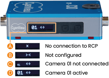
Check the network status on the CI0's LCD. Once the CI0 discovers the RCP, it shows
>-<. This means the RCP is reachable but the CI0 is not part of the configuration yet.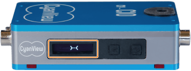
-
Connect the camera to the appropriate CI0 port. See the integration guide for your camera for setup and cable details. A mini camera can also be mounted directly on the CI0's top 1/4" screw, tightened from the bottom of the CI0 with a small flat screwdriver.
RCP Configuration
-
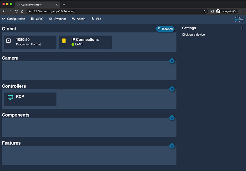
Access the RCP's Configuration Web UI. The diagram below shows a static configuration for an RCP with serial number
CY-RCP-18-34.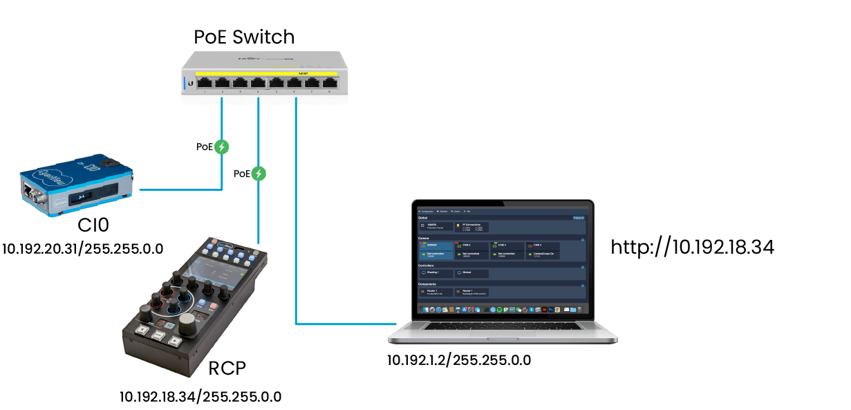
You should see the following page.
-
Add a camera: click the "+" button at the top right of the camera section. The new camera's properties appear in the right sidebar. Fill in these fields:
- Number: Camera number displayed on the RCP
- Name: Camera name displayed on the RCP
- Camera Head Model: Select your camera make and model from the list. An interface section appears.
- Interface Port: Select your CI0 in the list. The last digit indicates which CI0 connector (1 or 2) the camera is connected to.
-
Check that the camera is properly connected.
-
The camera icon in the Web UI turns green when the camera has been detected and configured.
-
The CI0 displays the camera number in bold (e.g. D) when the camera is communicating. If the number is small (e.g. C), the CI0 has been configured by the RCP but no communication can be established with the camera. Check the cable and connection, and the troubleshooting section of your camera's integration guide.
-
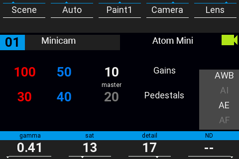
The camera icon on the RCP turns green when the camera is properly controlled. It stays red if communication with the camera can't be established.
-
Operation
The RCP should now be operational. A few tips to get started:
- The top row of buttons selects the top menu of the main LCD
- The bottom row selects the submenus (the second row of labels on the LCD)
- The Paint menu cycles through OFF → PAINT 1 → PAINT 2
- The "Menu" button shows status pages, including the IP address received by DHCP
- The left/right arrows at the bottom cycle between cameras
For details, refer to the RCP UI manual.
Software Updates
Product updates are delivered continuously, so it is a good idea to bring your system up to date at this point. Connect the switch to an internet access, a modem, or a 4G access point.
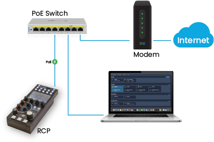
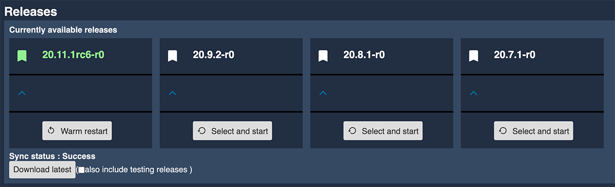
Once the RCP has internet access, it lists the available releases in the Admin tab of the Web UI. Clicking "Download Latest" refreshes the list. Click "Select and start" on the latest release to activate it. The release name indicates the release date: 20(year).11(month).1(number). The update takes roughly 30 seconds and automatically upgrades your configuration.
This updates only the software running on the RCP, not the full system. See Product Updates for keeping the full system up to date.