VP4 Configuration
Source
This content is based on Cyanview's official manuals. Always check the official page for the latest information and precise specifications.
https://support.cyanview.com/docs/Manuals/VP4Manual
https://support.cyanview.com/docs/Manuals/VP4Manual
VP4 can operate as a standalone unit through its dedicated Web UI, or it can be controlled from the RCP.
Configuring a VP4 Channel Alone
Follow these steps if you only want to control a VP4 channel on its own.
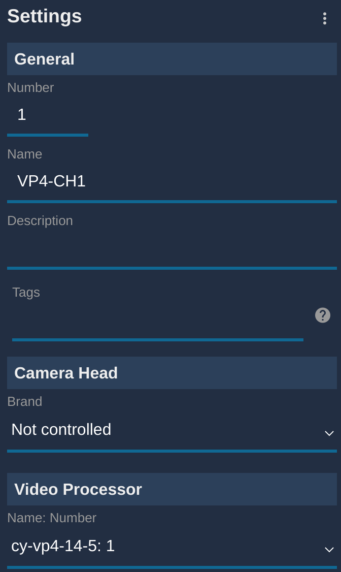
- Create a new camera with a number and name
- Under "Camera Head," select "No Control"
- In the "Video Processor" section, select the VP4 and channel (format:
SERIAL:CHANNEL_ID)
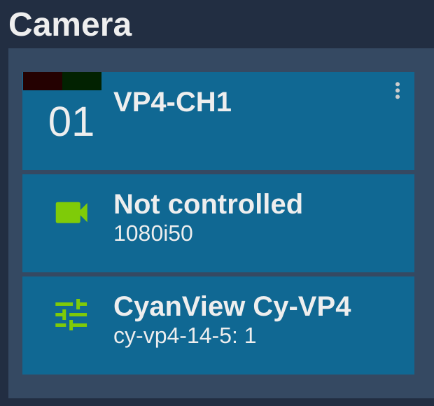
Once configured correctly, the block turns green.
Combining VP4 with Camera Control
Follow these steps if you want to control both the camera and the VP4.
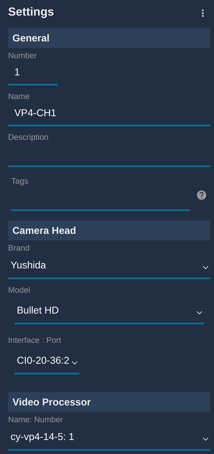
- Create a new camera with a number and name
- Select the camera brand and model from the list
- In the "Video Processor" section, select the VP4 and channel (format:
SERIAL:CHANNEL_ID)
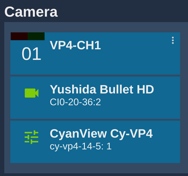
Once configured correctly, the block turns green.
Operation from the RCP
By default, camera head control takes priority over VP4 control. For example, if both the camera and the VP4 have a gain function, the camera's gain is controlled by default.
In this case, the RCP shows the following three buttons:
- CAM: Toggle camera head control
- POST: Toggle VP4 control
- C→P / P→C: Switch which of the camera or VP4 takes control priority
When Camera and VP4 Are Combined by Default
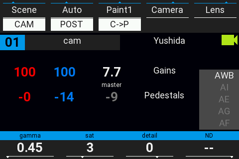
The camera and VP4 are combined with the camera taking priority (the VP4 only corrects functions the camera doesn't have).
RCP: Camera Only
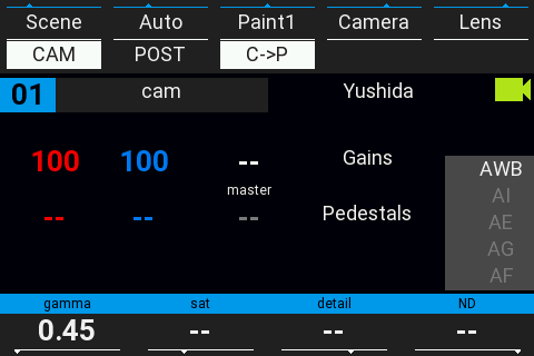
RCP: VP4 Only
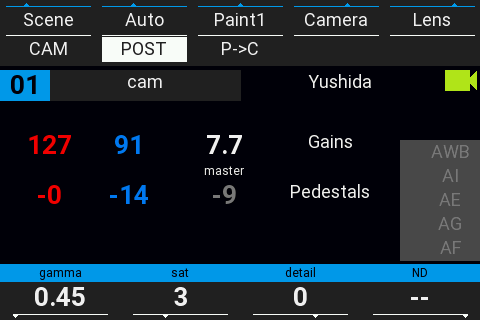
RCP: Camera and VP4, with VP4 Given Priority
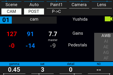
- P→C: Post (VP4) takes priority over camera control
- C→P: Camera takes priority over post (VP4) control
Vector Selection
Vectors are identified by numbers 1 through 16.
- GATE: Desaturates unselected colors and highlights the selected vector. It cannot be used while the camera is on-air, since it affects the main signal.
- Alternatively, pressing the "vect/peek" knob generates a small saturation burst on the selected vector, which can be checked on the vectorscope. This has minimal impact on the live picture.
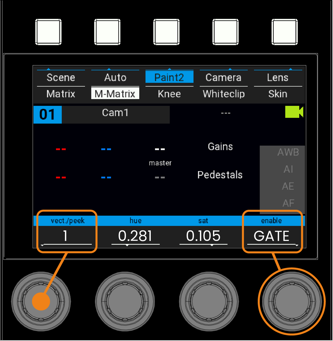
VP4 Controls
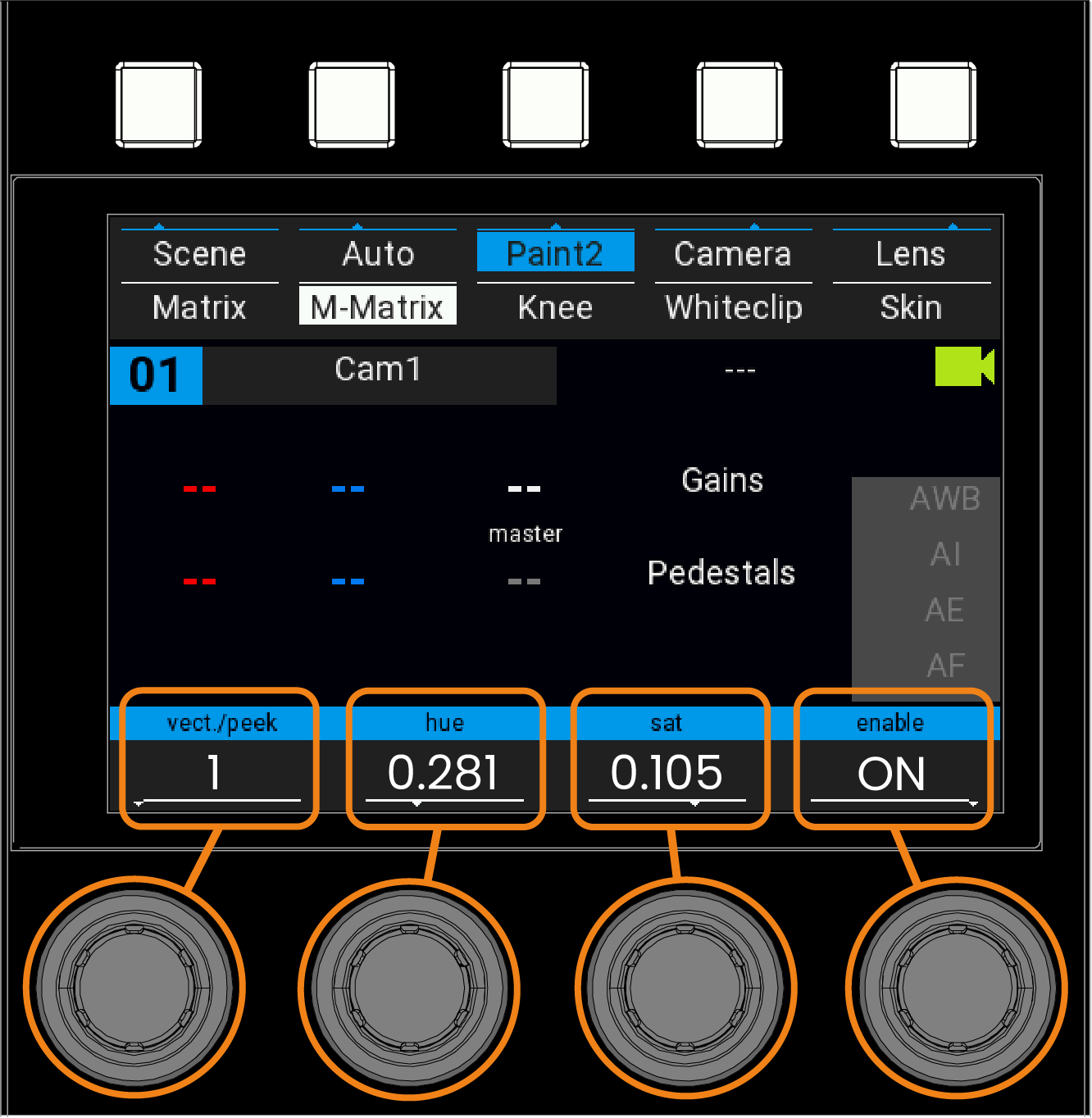
| Control | Description |
|---|---|
| vect/peek | Rotate to select the color vector you want to correct. Press to generate a saturation peak so you can identify the current vector on screen |
| hue | Rotate to change the hue of the selected vector |
| Saturation | Sets the saturation of the selected vector's color |
| enable | Rotate to switch between OFF / ON / Gate. GATE desaturates unselected colors to highlight the target vector, ON enables color correction, OFF disables color correction |